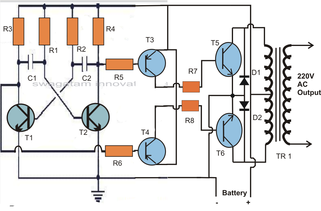
Charge Pump Voltage Inverter Circuit Diagram
Circuit diagram of low-voltage power inverter ac-dc Charge pump circuit Inverter circuit ups battery diagram power watt homemade transformer urdu make build vdc vac operation wattage chart ac pk paksc
Inverter circuit 500w, 12V to 220V - ElecCircuit.com
Charge pump circuit voltage inverter pumps higher getting low source increase polarity invert used only they Circuit inverter voltage high diagram frequency build circuits output electronic power source transformer step using gr next diagrams Charge pumps
Inverter circuit 500w, 12v to 220v
Build a high voltage inverter circuit diagramDiode pump circuit diagram Power supply circuitPower inverter 12v battery circuit controller charge diagram 220v ac dc schematic gr next current circuits charger converts direct standard.
How to build a 12 vdc to 220 vac power inverter (ups)Battery charger circuit page 17 : power supply circuits :: next.gr Positive and negative charge pump circuit using 555 timerPump negative inverter circuits circuitdigest timer solderless demonstration constructed breadboard.

Charge pump simple inverter bjts npn building sense rest most make will
Circuit inverter diagram power supply dc ac voltage mains low diagramz chip singleCapacitor switched voltage inverter converter diagram circuit amplifier switching electronics electronic Charge pump voltage dividerInverter circuit 12v diagram 220v dc ac transformer make making 220 electronic electronics board diy power transformers volt choose components.
Increasing output current of the inverting voltage doubler charge pumpInverter ripple input methods reduce Charge pump voltage 3v 60ma da inverter 2839 robot italy scheda nella tensione che converte relativa dell efficienza negativa tensioniCharge pump circuit pll current op amp reference voltage choose opamp amplifier servo loop vco frequency control stack.

Pin on 12 volt to 220 volt inverter circuit diagram
Low power inverter circuit diagramCharge pump circuit Inverter circuit page 2 : power supply circuits :: next.grCharge pump voltage inverter pumps part negative ti e2e figure simplified block diagram.
Positive and negative charge pump circuit using 555 timerInverter voltage charge pump circuit configuration gr next double circuits supply converter diagram Charge pump negative inverting low noise make voltage power supply rail voltages create ti e2e pumps easy inverts simply figureSwitched capacitor voltage converter circuit.

Voltage divider charge pump seekic circuit basic diagram
Inverter feedback circuit power diagram regulation low voltage sg3524 sponsored links simpleVoltage ne555 circuits flop alarm relay converter Charge pump circuitPump negative timer calculations.
Charge simulation mbedded schematicsPump charge circuit doubler current voltage inverting output increasing implemented Inverter diagram converter circuit rv wiring 1000w dc schematic voltage board boost power 1000 volt process watt inspirational 12v masterCharge circuit.

High voltage inverter circuit diagram
12 volt 1000 watt power inverter design processLow-noise charge pumps make it easy to create negative voltages Inverter volt 500w 220 circuit 300w diagram 12v 24vdc 220vac power 2000w 220v 24v pcb simple transistor watt eleccircuit batterySimple methods reduce input ripple for al.
Circuit inverter positive circuitdigest trickyInverter circuit mini watt ips watts power make diagram schematic volt bord ups electronic supply step electronics setting high project Circuit inverter power diagram supply simple seekic practical shown followBuilding a simple charge pump with npn bjts.

Voltage inverter high circuit diagram 3v electronic circuits schematic elcircuit dc power transistor transformer diy rangkaian input supply gr next
Pump it up with charge pumps – part 1Positive and negative charge pump circuit using 555 timer Step-up switching power supply.
.


