Circuit Diagram Of 3 8 Decoder
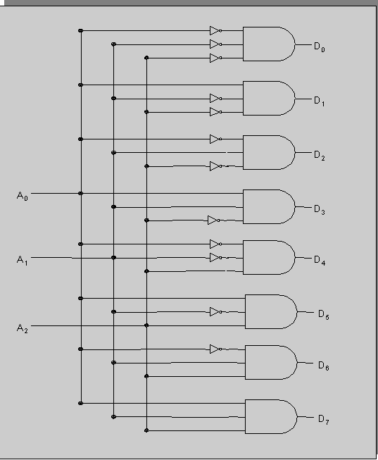
Decoder logic diagram and truth table / ks 0048 logic diagram of 3 to 8 Digital logic Decoder using circuit enable input diagram logic gate binary decoders scale small active code verilog combinational digital high circuits edwardbosworth
function - 4 to 16 decoder made by two 3 to 8 decoders not working
Decoder truth adder 3x8 multiplexer inputs outputs schematic gates demultiplexer circuits nand eight works segment How to design a 4 to 16 decoder using 3 to 8 decoder Decoder circuit with truth table
Combinational circuits and sequential circuits
Decoder circuit 16 using truth table enable high only designingWhat is a decoder? operation, types and applications Verilog for beginners: 3-to-8 decoderLessons in electric circuits -- volume iv (digital).
Binary decoders: basics, working, truth tables & circuit diagramsHow to design a 4 to 16 decoder using 3 to 8 decoder Decoder circuit line draw logic keep cool internal circuitryDecoder circuit line diagram electronics sample paper digital.
Decoder part15 ares fig15
Decoder functions showing three circuit logic did digitalDecoder circuits combinational sequential truth table diagram Decoder circuit with truth tableDecoder circuit 16 binary decoders truth diagram applications block two.
Sample paper of digital electronics and circuitDraw the circuit for a decoder and explain the working of this decoder Decoder table logicDecoder logic using circuits schemas.

Other circuits: decoders, multiplexers, and demultiplexers
Decoder diagram block verilog figure beginnersDecoder circuit diagram types operation block gates inputs two output which has will applications binary inverters provide Decoder circuit logic line decoders digital circuits combinational encoder show msi fashion switching theory electriccircuits kuphaldt ibiblioDecoder 16 two decoders circuit made properly working logic.
.


