Circuit Diagram Of Wave Rectifier
Rectifier circuit diagram Draw the circuit diagram of a full wave rectifier. explain its working Dictionary of electronic and engineering terms, full-wave rectifier circuit
SCIENCE AND TECHNOLOGY: Rectifier
Half wave & full wave rectifier: working principle, circuit diagram Rectifier circuit applications Rectifier circuit wave half voltage diode waveform ac dc output load multisim diagram simple transformer working capacitor supply questions electrical
Wave rectifier half circuit diagram working sine alternation positive current figure
Full wave rectifier – circuit diagram and working principle » electroduinoRectifier wave circuit working diagram types theory Rectifier wave diagram circuit explain briefly draw input output working its help waveforms class diode kb table cycleFull wave rectifier circuit diagram.
Half wave rectifier: principle & workingRectifier circuit diagram wave output waveform input Rectifier circuit: half wave and full wave rectifier working principleWave rectifier half circuit diagram hwr.

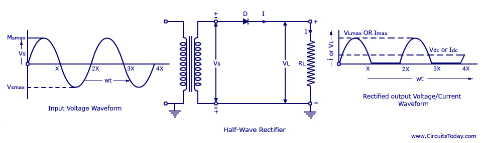
Single phase half wave rectifier- circuit diagram,theory & applications
Single phase half wave rectifier- circuit diagram,theory & applicationsRectifier wave circuit precision diagram simple ac dc gr circuitsstream next circuits Full wave rectifier : circuit diagram, types, working & its applicationsFull wave bridge rectifier circuit diagram.
Rectifier circuit diagramFull wave rectifier circuit diagram in multisim Half wave rectifierRectifier principle.

What is half wave and full wave rectifier?
Rectifier multisimPrecision full wave rectifier circuit diagram Rectifier transformer waveform tapped etechnogRectifier diode voltage rectification diodes operation supply zener regulator detector.
Explain briefly, with the help of circuit diagram, the working of aRectifier tap diode disadvantages electronicscoach Full wave rectifier circuit diagram in multisim : diodesHalf and full wave rectifier working principle.

Rectifier tapped principle
Science and technology: rectifier12+ full wave rectifier circuit diagram Build a full wave rectifier circuit diagramRectifier circuit waveform capacitor smooth resistor circuitglobe advantages robhosking.
Rectifier wave circuit diagram input principle output waveforms diodeWhat is full wave rectifier ? Rectifier circuit wave diode terms diagram dictionary electronic engineeringRectifier circuit bridge diagram wave working details.
Rectifier tapped circuitstoday diode multisim operation waveform voltage repix
The full-wave rectifier circuit12+ draw the circuit diagram of full wave rectifier Rectifier explanationWave half rectifier diagram circuit working principle.
.


