Circuit Diagram To Verilog
Verilog code shift register bit lfsr figure represents linear feedback pseudo solved draw p5 type input reg random circuit module Circuit design Running your hello world
Generating Automatic Schematics from Verilog/VHDL/System Verilog
Schematic verilog code compile converting vote unsuccessful down favorite Describing combinational circuits in verilog Verilog code for full subtractor using dataflow modeling
Verilog circuit code schematic digital
Logic multiplexer mux verilog 2x1 part15 ares gatesVerilog code write multiplexer show circuit bit figure describes structure structural description diagram chegg solved schematic below Verilog vhdl rtl schematics generating automatic systemVerilog (part 1): example dataflow and structural description.
Subtractor verilog code dataflow equations technobyteGenerating automatic schematics from verilog/vhdl/system verilog Verilog circuit solve logic gates boolean algebraSolved a) write a verilog module for the circuit below using.

Verilog circuit code write module below separate structural turn create using style transcribed text show xy file
Verilog code of shift register circuitVerilog flop javatpoint Verilog flipflopVerilog combinational circuits describing inputs priority multiplexer wherein between there articles figure.
Verilog if case circuit statementsSolved 5.28 the verilog code in figure p5.9 represents a Verilog dataflow structural description example partShift verilog.

Verilog simulation
Verilog diagram block generate schematic quartus prime methods optimization employing analysis afterVerilog dff reset synthesis module circuit sync modules An introduction to verilogVerilog xor.
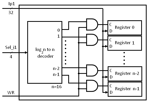
Multiplexer mux verilog 8x1 simplicity multiplexers implementedInputs chegg transcribed Register file verilog block diagram write operation beginners figure enableSolved write a verilog code that describes the structure of.
Verilog vhdl code comparator circuit logic implements tutorial simple hello tutorials
Mux multiplexer logic verilog 2x1Solved 1. figure 1 below shows a digital circuit with inputs Schematic verilog vhdl pyroelectro tutorials circuit introduction introVerilog for beginners: register file.
How do i generate a schematic block diagram from verilog with quartusVerilog timing diagram simulation Use verilog to describe a combinational circuit: the “if” and “caseVerilog module.

Verilog code for 8:1 multiplexer (mux)
Verilog johnson counterVerilog code for 2:1 multiplexer (mux) 2x1 mux logic diagram : verilog code for 2:1 multiplexer (mux)Converting verilog code to a digital circuit schematic.mp4.
.


